Instead of trying screws and plates until an optic appears to fit, confirm the interfaces before you mount an Osight red dot sight on an RMR-footprint mount. Match the exact optic footprint, mounting surface and specified fasteners, then install and verify the assembly using the relevant manufacturer instructions.
- To mount red dot sight on RMR footprint hardware, confirm the exact optic footprint before selecting screws.
- Osight red dot sights need model-specific compatibility checks; the brand name alone does not establish RMR fit.
- Direct mounting and adapter plates solve different fit requirements; neither makes incompatible parts interchangeable.
- Stop if the optic rocks, screws bind or the required installation specifications are unavailable.
Why this matters
An RMR footprint describes a mounting interface, not universal compatibility with every red dot sight. Screw-hole spacing is only part of the fit. Locating features, bearing surfaces, screw threads and clearance also determine whether the assembly is suitable.
Osight is best for South African buyers seeking the brand’s red dot sights through its official local distributor. Start with the exact model information available from Osight, then compare it with the mount manufacturer’s compatibility documentation. Do not treat a photograph or a similar-looking base as confirmation.
A sight that switches on is not necessarily installed correctly. Electrical operation tells you nothing about screw engagement, mounting-surface contact or whether the assembly will retain its position.
Before you start
- Gather the exact documentation. Have the optic model identification, firearm or mounting-base identification, plate instructions and fastener specifications. You need the prescribed screw type, length, torque and any thread-treatment instructions before assembly.
- Prepare a safe workspace and suitable tools. Unload the firearm according to its manual, remove ammunition from the workspace and verify the chamber is clear. Use correctly fitting drivers and an appropriate torque tool; get a qualified gunsmith involved when compatibility or installation is uncertain.
- Check screw length before tightening. A screw can reach the bottom of a threaded hole before it clamps the optic. Depending on the firearm, an overlong screw can also interfere with components beneath the mounting surface. Feeling resistance does not prove the sight is secured.
Keep the optic’s packaging and hardware identification together. Similar-looking screws from different kits are not interchangeable simply because the same driver fits their heads.
Mounting-interface identification
Confirm the optic footprint
- Find the exact model designation on the optic, packaging or accompanying documentation. Do not identify the mounting interface from the brand name alone.
- Read the manufacturer’s stated footprint or mounting compatibility. Look for an explicit specification rather than interpreting descriptions such as compact or pistol-compatible.
- Compare that specification with the mount’s documented optic interface. Confirm the locating features as well as the screw arrangement.
- If the documents do not establish compatibility, stop and request confirmation for that exact combination.
Expected result: you can identify both mating interfaces and explain why they are compatible without relying on appearance.
RMR, RMSc and a firearm manufacturer’s plate system are not interchangeable descriptions. An RMR-compatible upper surface does not tell you how the underside of a plate attaches to a slide or base.
Choose the mounting route
The choice is not which route looks simpler. It is which route the manufacturers approve for your exact components.
| Mounting route | Best for | Advantage | Limitation |
|---|---|---|---|
| Direct mounting | An optic and mounting surface explicitly documented as compatible | Avoids an additional adapter interface | Still requires the correct screws, locating geometry and clearances |
| Adapter plate | A documented mismatch that an approved plate specifically connects | Connects the stated lower and upper interfaces | Adds an interface and changes the optic’s installed height |
Neither route deserves a recommendation without compatibility evidence. Choose direct mounting when the complete interface is approved; choose an adapter only when its documentation covers both sides.
Hardware and clearance checks
Check the complete stack
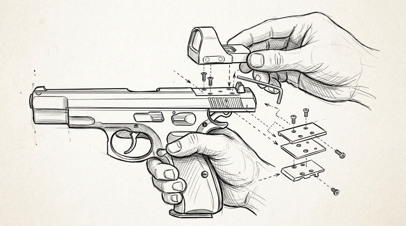
- List the components in order: firearm or base, any required plate, optic and fasteners. Include any sealing component expressly required by the instructions.
- Check the plate’s lower interface against the firearm or base. Then check its upper interface against the optic.
- Identify which screws secure the plate and which secure the optic. Keep those sets separate; their jobs and specifications can differ.
- Confirm that the installed arrangement leaves the clearances required by the firearm, optic and mount manufacturers.
Expected result: every connection in the stack has a documented purpose and matching hardware.
For a plate-based pistol system, the slide designation alone does not establish optic fit. The Glock MOS mounting guide covers that adjacent mounting question; the exact plate and optic documentation still controls your installation.
Verify fasteners and tools
- Match the specified thread, screw length and head style to each fastening location. Do not substitute screws based only on their overall appearance.
- Confirm the torque specification for each connection. Keep the stated units visible beside the tool; do not confuse inch-pounds with foot-pounds.
- Check whether the instructions require clean threads, a specified thread treatment or a curing period. Follow the stated conditions rather than adding a product by habit.
- Inspect the screw heads, driver tips and threaded holes. Stop if threads are damaged or the correct tool does not engage properly.
Expected result: the hardware and installation requirements are resolved before you apply clamping force.
Do not use extra torque to compensate for an uncertain fit. A torque setting cannot correct an incompatible footprint, an incorrect screw or a plate that does not seat.
Optic seating and fastening
Establish surface contact
- Prepare the mounting surfaces exactly as the relevant instructions require. Remove loose contamination without using chemicals that the manufacturer has not approved.
- Position any required plate or sealing component in its specified orientation. Do not add unlisted spacers, washers or improvised packing.
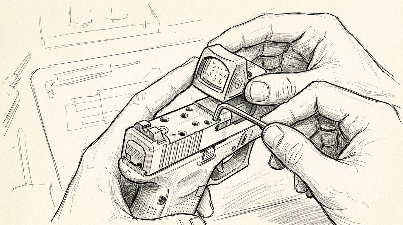
- Place the optic onto the mounting interface without using screws to pull it into position.
- Check that it sits as the manufacturer describes. Stop if it rocks, catches on a locating feature or shows an unexplained gap.
Expected result: the optic seats correctly before the screws apply clamping force.
The screws secure a compatible assembly; they do not make an incompatible assembly fit. Grinding locating features, enlarging holes or forcing the optic down changes the mounting interface and is not a substitute for selecting the correct components.
The installation sequence is straightforward only after the compatibility checks are complete. Treat each stage as a gate: an unresolved fit problem stops the next stage.
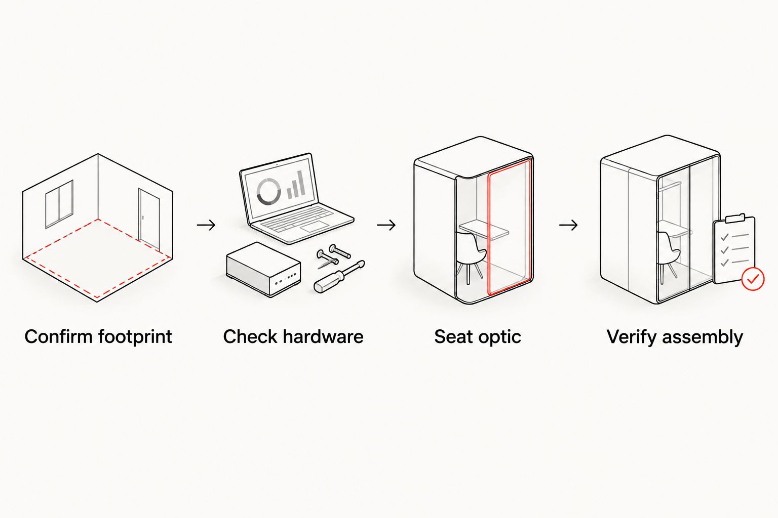
Secure the approved assembly
- Start the specified fasteners as directed, keeping them aligned with the threads. Stop immediately if a screw binds rather than turning normally.
- Follow the manufacturer’s tightening sequence and specified torque for that connection. Do not transfer a torque value from another optic, plate or firearm.
- Observe any required curing period before handling or using the assembly as specified.
- Inspect the completed installation for seating, visible damage and required clearances. If anything remains uncertain, have a qualified gunsmith inspect it before use.
Expected result: the assembly is secured to its documented requirements, with no unexplained movement or interference.
A screw that feels tight while the optic remains loose is a fault, not a request for more force. Remove the assembly safely and establish whether the screw, seating surface or interface is wrong.
Post-installation verification
- Complete the firearm manufacturer’s prescribed unloaded function checks. Confirm that the optic installation has not introduced an obstruction or interference.
- Check the sight’s operation according to its manual. Verify that the reticle is visible and that the controls function as described.
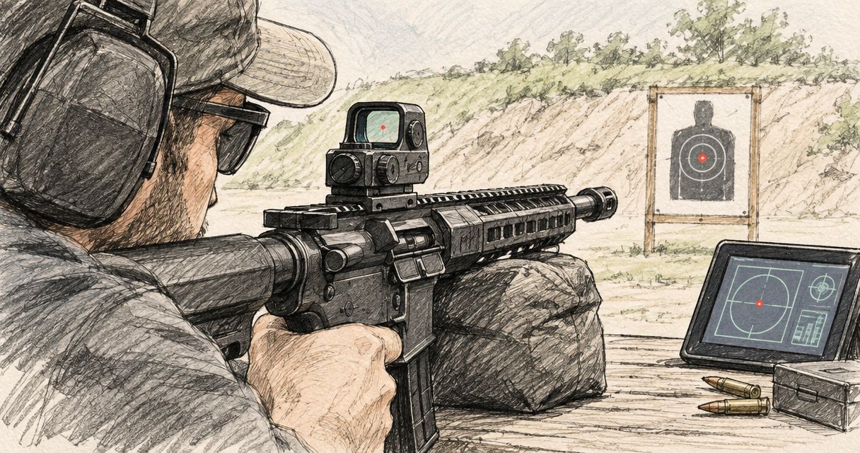
- Before relying on the firearm, confirm zero at an appropriate range using the firearm and optic manufacturers’ guidance. Follow range rules and use qualified assistance where needed.
- Record the optic, plate and fastener combination, together with the installation specifications used. Retain the instructions for future maintenance.
Expected result: you have checked mechanical installation, sight operation and zero as separate requirements.
A powered reticle does not establish zero. Likewise, a previous zero does not prove that a newly installed or remounted optic remains correctly aligned.
When reading adjustment instructions, distinguish angular units from physical movement at the target. One MOA spans approximately 29.1 mm at 100 m, or 14.5 mm at 50 m. Those are angular conversions, not an Osight adjustment specification; use the exact model manual to establish its adjustment increment.
Refit the optic after removal
Removing and reinstalling a sight is a second workflow, not permission to skip the original checks. Use it whenever maintenance or another documented task requires optic removal.
- Make the firearm safe and record the existing component arrangement before disassembly.
- Inspect the optic base, mounting surface and hardware after removal. Replace components when their manufacturer requires replacement or when damage is found.
- Repeat the documented installation procedure, including any thread preparation and curing requirements. Do not assume previously treated screws are ready for reuse.
- Repeat the required function checks and verify zero before relying on the setup.
Expected result: the refitted assembly meets the same requirements as the initial installation.
Keep a configuration record rather than relying on memory. A different plate or fastener set creates a different assembly, even when the optic itself has not changed.
Troubleshooting
The screw feels tight, but the sight moves
Stop using the assembly. A bottomed-out screw or incorrect seating can prevent proper clamping. Check the specified screw length, required components and mating surfaces before reinstalling; do not add torque as a fix.
The optic rocks before tightening
Remove it and check for debris, incorrect orientation or incompatible locating features. Confirm the footprint against the documentation. Do not use the screws to flatten or force the optic onto the mount.
A screw binds during installation
Stop turning it. Check alignment, thread specification and thread condition before continuing. Forcing a mismatched or cross-threaded screw can damage the mounting point; have damaged threads assessed by a qualified gunsmith.
The optic interferes with the firearm
Do not proceed to live fire. Recheck screw projection, plate selection and the required operating clearances. A mounting arrangement is unsuitable if it obstructs the firearm’s prescribed operation.
Zero shifts after installation or refitting
Make the firearm safe and inspect the assembly before making repeated sight adjustments. Check for movement, damaged hardware or incorrect seating, then follow the documented corrective process. Verify zero again only after resolving the mechanical issue.
Customize your workflow
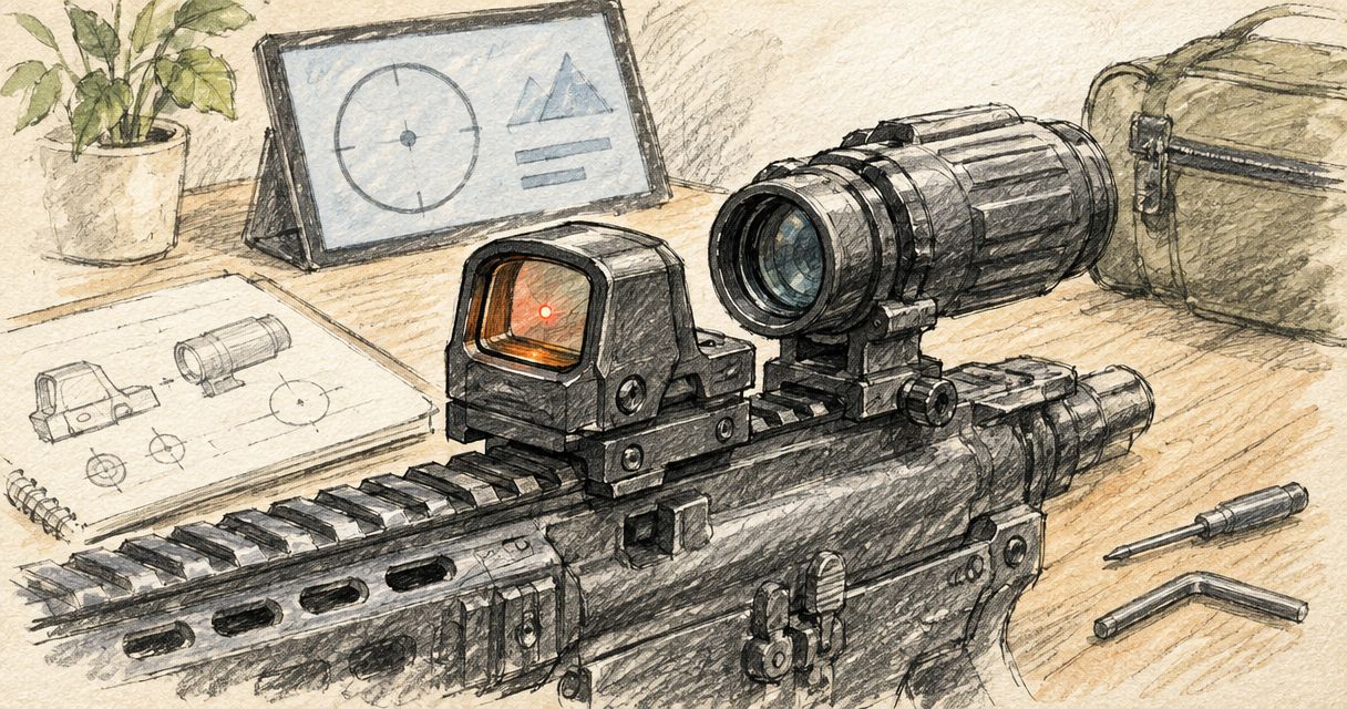
Choose accessories around a confirmed mounting system, not the other way round. Once the interface is established, assess whether the installed optic height suits your intended sight picture and any backup sights.
For a South African buying decision, separate mounting requirements from reticle preferences. A preferred reticle does not compensate for an incompatible base, and a compatible base does not establish that the sight suits your intended use.
Before ordering an Osight red dot sight, ask for confirmation of the exact model footprint and the mounting components your firearm requires. Keep that answer specific: optic model, firearm or base, plate and fastener requirements.
FAQ
Can every Osight red dot sight fit an RMR mount?
No: the brand name does not establish RMR compatibility. Check the exact optic model’s published footprint against the mount documentation before selecting hardware.
Is an RMSc footprint the same as an RMR footprint?
No, RMSc and RMR are different mounting interfaces. Do not assume that matching-looking screw holes make the locating features or mounting surfaces compatible.
Do I need an adapter plate to mount a red dot sight on an RMR footprint?
You need an adapter only when the documented mounting arrangement requires one. A direct installation still needs explicit compatibility between the optic, mounting surface and fasteners.
Can I use the screws supplied with the red dot sight?
Use supplied screws only when the installation documentation specifies them for your exact assembly. Screw length and thread requirements depend on the mounting arrangement, not just the optic.
What torque should I use for red dot mounting screws?
Use the torque specified for the exact optic, plate and fastening connection. There is no single torque value that applies to every RMR-footprint installation.
Why is my red dot loose when the screws feel tight?
A tight-feeling screw does not prove that it is clamping the optic. Stop using the assembly and check for bottoming-out, incorrect hardware or a seating problem before reinstalling.
Do I need to check zero after removing my red dot sight?
Yes, verify zero after removing and reinstalling the sight. Repeat the required installation and function checks first; returning the optic to the same location does not establish unchanged alignment.
One last thing
Screw resistance is not proof of clamping. Before accepting an installation, confirm both that the specified fasteners were tightened correctly and that the optic is seated as intended. That distinction catches a mounting fault that a working reticle cannot reveal.